- Software
- Open access
- Published:
val3dity: validation of 3D GIS primitives according to the international standards
Open Geospatial Data, Software and Standards volume 3, Article number: 1 (2018)
Abstract
The validity of 3D primitives in 3D GIS datasets is often a prerequisite for using them in simulation and decision-making software, e.g. visibility analysis, noise pollution assessment, and energy estimation. However, while agreed definitions exist (in the international standard ISO19107), most software vendors ignore them and implement simpler 3D primitives, for instance by excluding interior boundaries in surfaces and/or solid. Such limitations prevent practitioners from exchanging and converting datasets, and thus to use these in other software and applications.
I present in this paper val3dity, an open-source software to validate 3D primitives according to the international definitions of ISO19107. Practitioners can use it directly, without limitations: its code is freely available under the GPLv3 license, both binaries and a web-application are publicly available. It takes as input several formats (including the international standard CityGML), and outputs a report that helps users identify and understand the errors.
I describe some of the engineering decisions supporting val3dity, and show that it can be used to validate real-world datasets.
Introduction
Three-dimensional GIS datasets, containing volumes and surfaces embedded in 3D, are being increasingly used as input in different applications, see Biljecki et al. [4] for an overview. The 3D GIS community is mostly focused on 3D city models (such as CityGML [11, 23] and IndoorGML [15]), but there are other 3D representations used, e.g. GeoSciML [26]. As highlighted by Biljecki et al. [5], in practice the quality of available 3D datasets is often poor: they contain geometric and topological errors, e.g. duplicate vertices, missing surfaces, self-intersecting volumes, etc. Often these errors are not visible at the scale the datasets are visualised [18], and, as a consequence, practitioners are not aware of the problem. In most cases, these errors prevent us from using the datasets in other software and applications, see Nouvel et al. [21], Steuer et al. [28], and Bruse et al. [8] for concrete examples. However, it should be noticed that, even for visualisation purposes, errors can be problematic since the shading/colouring of surfaces is often based on the orientation of their normals. We can assume that errors in 3D models are very common since: (1) McKenney [20] reports that practitioners using 3D CAD models for finite element analysis applications spend as much as 70% of their time fixing the input models; (2) there is a growing field of science that deals with the automatic repair of single 3D models [3].
I present in this paper the new and extended version of val3dity (version 2.0), an open-source software to validate 3D primitives according to the international definitions. As explained below, val3dity builds upon its first version in which only single solids were validated; the details of the original methodology are given in Ledoux [19]. The main extension presented in the following is that all the 3D primitives defined in ISO19107 [14] are now supported: MultiSurface, CompositeSurface, Solid, MultiSolid, CompositeSolid. Unlike other implementations, val3dity fully supports interior boundaries for both surfaces and for solids, and also the interactions between different solids can be validated. The only restriction is that edges need to be linear, and surfaces planar. This is a common restriction in the GIS world (CityGML does not support curves arcs and parametric surfaces) and primitives from other fields (IFC) can always be discretised into linear/planar ones. Furthermore, val3dity supports a few GIS input formats, the validation reports have been designed to help users easily identify errors, and the validation of CityGML BuildingParts (namely their topological interaction with others) is now supported.
Background
Definitions of 3D primitives in ISO19107
ISO19107 [14] has the following geometric primitives for representing its objects: a 0D primitive is a GM_Point, a 1D a GM_Curve, a 2D a GM_Surface, and a 3D a GM_Solid. A d-dimensional primitive is built with a set of (d−1)-dimensional primitives, e.g. a GM_Solid is formed of several GM_Surfaces, which are formed of several GM_Curves, which are themselves formed of GM_Point.
Geometric primitives of the same dimensionality can be combined together into another primitive, namely:
-
aggregate: a collection of primitives of the same dimensionality that is simply used to bundle together geometries. An aggregate does not prescribe any topological relationships between the primitives, they can overlap or be disconnected.
-
composite: a collection of d-dimensional primitives that form a d-manifold, which is a topological space that is locally like a d-dimensional Euclidean space (\(\mathbb {R}^{d}\)). A concrete example would be a composite of surfaces (2-manifold): each surface is a 2-manifold, and all the surfaces together also form a single 2-manifold. This implies that they are not allowed to overlap and/or to be disjoint.
Definitions of 3D primitives in val3dity
While the ISO19107 primitives do not need to be linear or planar, i.e. curves defined by mathematical functions are allowed, for val3dity, as in CityGML and most 3D GIS packages in use, the following two restrictions are used:
-
GM_Curves can only be linear
-
GM_Surfaces can only be planar
In the following, the GML nomenclature [22] is followed for naming the primitives: an aggregate is a Multi* and a composite is a Composite*. The following 3D primitives are thus supported by val3dity:
-
MultiSurface
-
CompositeSurface
-
Solid
-
MultiSolid
-
CompositeSolid
Figure 1 shows the 3D primitives that val3dity supports; LinearRings are linear GM_Curves, and Polygons are planar GM_Surfaces.

The 3D primitives supported by val3dity. Light blue primitives are those representing interior boundaries. A Shell is not validated explicitly (no input possible), but it is implied as the boundary of a Solid
A CompositeSurface that is closed (it does not contain any boundary; it is ‘watertight’) and orientable is referred to as a Shell. Shells are the basis to define the boundaries of a Solid; notice that in the figure the Solid has two Shells: one representing the exterior boundary (the cube in grey) and one the interior one (the cube in light blue), the latter defines a ‘void’ in the solid. The boundaries of a Solid are allowed to interact with each other under certain rules, these are explained in details in Ledoux [19].
A MultiSolid is an aggregate of Solids, and they are allowed to intersect and/or be disconnected.
A CompositeSolid, formed by the SolidsA and B, should fulfil the following two assertions:
-
Assertion #1: their interior should not overlap (Ao∩Bo=∅)
-
Assertion #2: their union should form one solid (A∪B= one Solid)
Related work
In this section I only discuss the existing validation software, and the scientific papers for which there is an implementation available (and thus ignore purely theoretical solutions). The first thing to notice is that while many commercial GISs offer surfaces embedded in 3D as primitives, they rarely offer volumetric primitives. Volumes are often represented with the equivalent of a MultiSurface, i.e. a set of surfaces embedded in 3D which could, or not, form a volume.
ArcGIS ProFootnote 1 is one such example, it contains a function (called isClosed()) to verify whether a set of surfaces forms a closed volume. This does not support interior shells, and the documentation does not specify whether self-intersection is verified or whether non-manifoldness is taken into account. Also, errors in each surface are not validated, one would have to project each of them to a 2D plane and run the 2D validation functions separately. Aggregates and composites are not handled.
Oracle SpatialFootnote 2 has a volumetric primitive that can contain interior shells, but unfortunately there are two major omissions that make this primitive diverts from the ISO19107 definitions: (1) Oracle’s shells are not 2-manifold, they simply have to be interior-connected (non-manifold vertices and edges are thus allowed); (2) Polygons cannot have interior rings. In two scientific papers describing the details of Oracle’s validation capabilities in 3D, Colley et al. [9] and Kazar et al. [16] falsely claim that this definition is ISO19107-compliant, while most of the figures clearly indicate otherwise; tests I ran with Oracle Spatial also confirms this. CompositeSolids are listed as 3D primitives in the documentation, but since the volumetric primitive used to build them are not following the international definitions, the CompositeSolid does not either.
CityDoctorFootnote 3 contains validation functions, although its primary goal is automatic repair of buildings stored in CityGML. According to the papers explaining the details of the software [1, 2, 29], the only volumetric primitive used is restricted to having only an exterior shell (interior ones are disallowed), and interior rings in Polygons are disallowed.
The transformer GeometryValidator in Safe’s FMEFootnote 4 supports the validation of ISO19107-compliant Solids because the first version of val3dity is used in the background. Aggregates and composites are however not currently supported.
An OGC Quality Interoperability Experiment about CityGML was carried out a few years ago, and contains more details concerning the validation capabilities of different software [24], although interior boundaries in Solids, as well as aggregates/composites, were ignored.
Implementation
Primitives are validated hierarchically
The methodology to validate the five different 3D primitives, as defined in the previous section, follows the methodology described in Ledoux [19] for single Solids, and extends it so that MultiSolids and CompositeSolids are handled.
The methodology uses many of the internals of the CGAL libraryFootnote 5 to represent and validate the 3D primitives, and uses existing methods to validate the 2D primitives. Because the geometric types and modules of CGAL do not follow the definitions of ISO19107, the geometric types available in different packages were modified and combined. One example is that a Solid is represented by a list of Shells (which are CGAL::Polyhedron_3), and the interactions between the different shells are validated with my own code using the Boolean operations in CGAL::Nef_polyhedron_3.
As Fig. 2 shows for one CompositeSolid, the 3D primitives are validated hierarchically:
-
the lower-dimensionality primitives (the LinearRings and Polygons) are validated by first projecting them to a 2D plane (obtained with least-square adjustment), and then using 2D validation methods;
Fig. 2 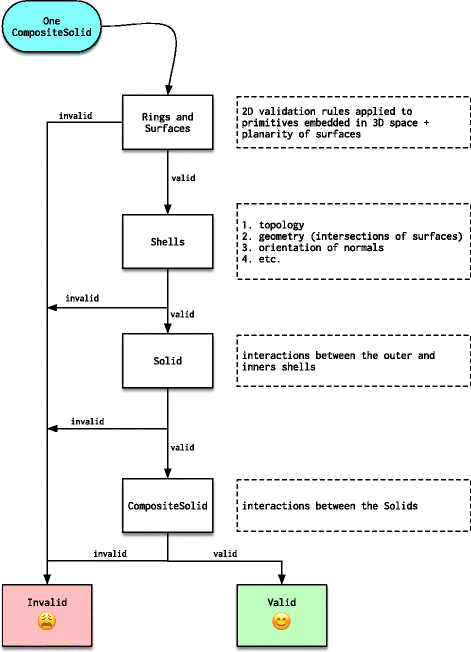
The hierarchical workflow used by val3dity to validate one CompositeSolid
-
then these are assembled into Shells and/or surfaces, and their validity is analysed;
-
then the Solids are validated (e.g. the interactions between different Shells, the orientation of the normals, etc.)
-
finally, for CompositeSolids, the interactions between the Solids are analysed.

This means that if one Polygon forming a CompositeSolid is not valid, the validator will report that error but will not continue the validation at the next level (to avoid “cascading” errors); all the primitives at one level are however validated.
At each level, the validator can report different error codes. As Fig. 3 shows, there are in total 32 different codes. Notice also that there are other errors:
-
errors related to specific City Objects in the CityGML data model [11, 23]. Currently these are only for CityGML Buildings, but they will be in the future extended to other classes if there is a need from practitioners. And also other standards will be included, e.g. IndoorGML is currently under development.
Fig. 3 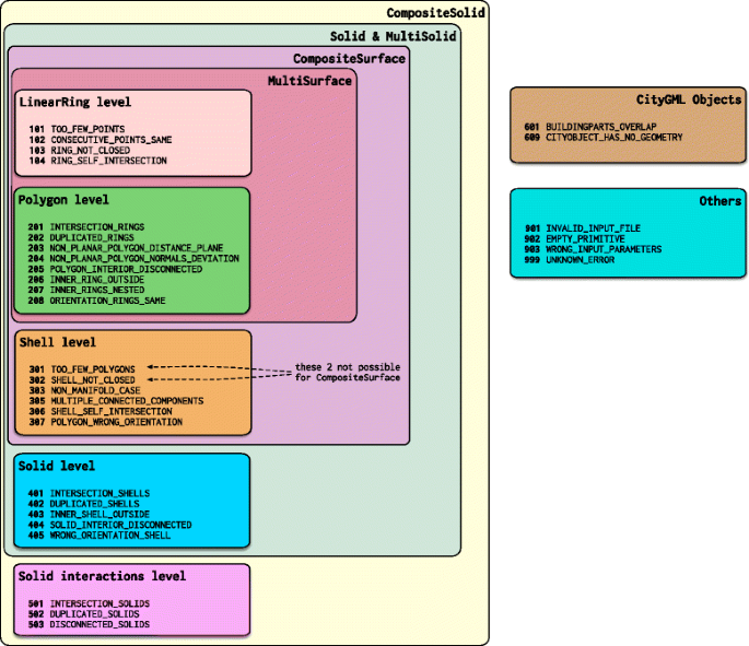
The 32 error codes of val3dity
-
input errors, e.g. with files that do not respect the schema. These are common in practice, and can influence the validation process [24, 30].

A fast C++ implementation
The source code of val3dity is freely available under the GNU General Public License v3.0. Compiling binaries for macOS, Linux, and Windows is easy; for Windows executables are even offered. It is written in C++ and uses these two open-source libraries: (1) CGAL library to represent some 3D primitives (as explained above); (2) GEOSFootnote 6 is used to perform the validation of the 2D primitives, the error codes (eventually) thrown by GEOS are mapped to the error codes of val3dity.
CGAL was chosen because it contains several of the building blocks required to implement a validator, and because it offers the possibility to use exact arithmetic for all the packages [31]. Besides the basic components of CGAL, the following packages are used:
-
2D Polygons: used to represent each ring of a Polygons;
-
2D Triangulation: in val3dity all the surfaces are triangulated with a constrained Delaunay triangulation [7], which allows us to support interior rings in Polygons and helps in catching complex cases of planarity [13];
-
3D Polyhedral Surfaces: used to represent one Shell;
-
3D Boolean Operations on Nef Polyhedra: used to represent one Solid and to model and verify the interactions between the Shells, but also the interactions between the different Solids of a CompositeSolid and the different parts of a Building;
-
3D Minkowski Sum of Polyhedra: used when a tolerance is used to validate CompositeSolids and BuildingParts (see the section below);
How to use it. val3dity is a command-line program only, there is no graphical interface (see Fig. 4). Several parameters can be set by the users, these are mostly related to the tolerances that val3dity uses. Indeed, while both ISO19017 and CityGML mention that each Polygon must be planar, the concept of tolerance is not mentioned. Tolerances for the following can be defined:
-
planarity of Polygons: the tolerances used have been agreed upon by the community in the OGC Quality Interoperability Experiments [24];
Fig. 4 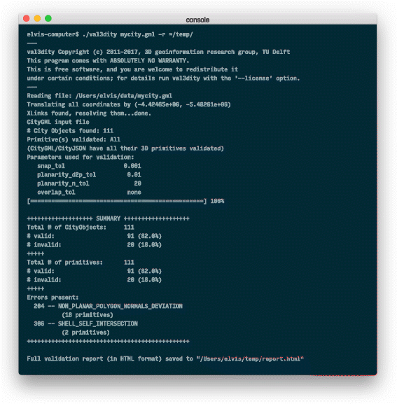
val3dity is a command-line only software
-
snapping between vertices: since in many formats, e.g. GML, the same vertex needs to have its coordinates listed for each Polygon, a tolerance must be used to identified if they are the same;
-
overlap between Solids or BuildingParts, as explained below.

As an alternative to the command-line interface, one can use the web-application of val3dity (see Fig. 5), which is freely available to everyone (there is however a maximum file size that can be uploaded).

val3dity has a web-application publicly available
Input formats. The following formats can be used as input: CityGML, CityJSONFootnote 7, GML file of any flavour, OBJFootnote 8, and OFFFootnote 9. For CityGML and CityJSON files, all the City Objects (e.g. Building or Bridge) are processed and all their 3D primitives are validated. Other GML files are simply scanned and their 3D primitives are validated according to the rules in ISO19107, all the rest is ignored. For OBJ and OFF files (formats without semantics and used mostly for visualisation), each primitive will be validated according to the ISO19107 rules, therefore one must specify how the primitive(s) should be validated (as MultiSurface, CompositeSurface, or Solid).
Interactions between solids are validated with a tolerance
A CompositeSolid, formed for instance by the SolidsA and B, should fulfil the 2 assertions defined in the ‘Background’ section. While these can be verified with Boolean operations, in practice we often encounter datasets where two Solids overlap (or are disjoint) by a very small amount, e.g. the overlapping volume would be around 10cm 3 for a Building. While the overlap is an error, in practice reporting this as an error can be a nuisance for the user.
val3dity therefore uses the concept of an overlap tolerance to validate CompositeSolids. This can be seen as a generalisation to 3D of the tolerance used for the 2D validation of polygon, see for example van Oosterom et al. [25]. As shown in Fig. 6, the mathematical morphology theory in 3D [27] is used to erode and dilate Solids by a user-defined parameter. Erosion is performed when the overlap between Solids is verified (Ao∩Bo=∅), and dilation when disjointness is verified (A∪B= one Solid). These operations are realised by a series of operators that uses the Minkowski sum of a Solid with a structuring element (a cube or dodecahedron in this case); as shown in Boeters et al. [6] and Donkers [10] the shape of the element will influence the resulting shape and thus the results. The perfect structuring element would be a sphere (would not yield errors, as an approximation by a dodecahedron does), however the closer the structuring element approximates a sphere the more computation time will be necessary.

Example of how the tolerance is applied when validating a CompositeSolid containing 2 Solids
Buildings having one or more BuildingParts can also be validated with an overlap tolerance. However, only the overlap assertion is verified, since BuildingParts are allowed to be disjoint; the CityGML standard is not clear about this, but this was confirmed as the intended behaviour [17].
It should be noticed that using an overlap tolerance when validating slows down the process since the implementation of the Minkowski sum in CGAL runs in O(n3 m3) time in the worst case [12], where n and m are the number of primitives (of any dimensionality) in the input (the Solid and the structuring element). This can be observed in the experiments with real-world datasets in the next section.
Reporting errors to the user
Some validators, in 2D and 3D, report only the first error encountered, and then stop. This can be frustrating and time-consuming for the user because she needs to fix the error and rerun the validation again. val3dity was designed to avoid this, and aims at validating as many parts of a 3D primitive as possible, but stops to avoid so-called ‘cascading errors’, i.e. errors that do not exist but are cause by another error. This is why a hierarchical validation is used, as previously explained. For each error, extra information is usually given, for instance: (i) if a Shell contains a hole, its location is provided; (ii) if a Polygon forming a Solid is invalid, then its identifier is reported (and if it does not have one then its position in the input file is reported); (iii) if two Solids in a CompositeSolid overlap, the identifiers of the Solids are reported, etc. val3dity outputs a validation report, in JSON format, where for each (CityGML) object and 3D primitive the validation errors are listed. The report is both human- and machine-readable. As shown in Fig. 7, it is also possible to navigate this report with an interactive HTML viewer containing a summary and a list of detailed errors for each primitive and object.

An example of an HTML report. Left: the summary report; Right: the details for each Building in a CityGML file
Results
How is the validator validated?
A comprehensive suite of tests to validate val3dity was implemented, it builds upon and extends the results of the OGC Quality Interoperability Experiments [24]. It uses the Python pytest frameworkFootnote 10 and a custom setup, and tests, among others:
-
all the error codes one by one; there are several files and each of them contains one and only one error, see Fig. 8 for eight randomly chosen cases;
Fig. 8 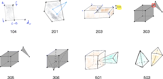
A few examples of unit tests for Solids, the numbers refers to the errors in Fig. 3
-
empty files and geometries, invalid input file formats. It should be noticed that val3dity does not validate the schema of the input, the main reason is that often small errors are not an issue for the validation and val3dity can recover from them (in the same way that a web browser can often display invalid HTML);
-
various valid geometries, larger files and boundary conditions;
-
command-line user input.

All the tests can be automatically ran after compilation, which ensures that val3dity is ISO19107-compliant on different operating systems.
Testing with different real-world 3D city models
To demonstrate that val3dity is useful in practice, I have chosen four 3D city model datasets, in CityGML, that are available as open data; a list of all open 3D city models is available at https://www.citygml.org/3dcities/. The aim of this section is not to perform a thorough analysis of the errors that were reported by val3dity, but rather to demonstrate that it can be directly used by practitioners for their daily work, and to demonstrate some of the validation options that are available. The four datasets are listed in Table 1 and shown in Fig. 9, they are all subsets of bigger datasets, and their exact area/file is specified. The tests were performed on a “standard laptop”: a MacBook Pro 2.2GHz Intel Core i7, 16GB of main memory, and an SSD harddrive.

The four datasets used for explaining the validation process
For each of the four datasets, the command used to validate it is explained below. All were validated with the option ‘–report_json report.json’ so that a report is generated, and the default values were used:
-
snap tolerance: 1mm
-
planarity tolerance (distance-to-plane): 1cm
-
planarity tolerance (normals orientation): 20 degrees
-
overlap tolerance: unused/0cm; and as explained below with 5cm too
Notice that all of the datasets can be read directly by val3dity, i.e. without any format conversion necessary as a pre-processing. Furthermore, the XLinks are resolved, but only if they point to other elements in the same file; external URIs are not resolved.
Berlin dataset is a large file (nearly 1GB) that contains more than 22,000 Buildings (with, oddly, only 3 having BuildingParts). Some of these are stored as Solid, and for some only semantic surfaces are stored, without any geometry defined. For the second case, we can assume that the meaning was that the semantic surface should be represented as a MultiSurface, and thus val3dity offers that option on-the-fly (‘–geom_is_sem_surfaces’). Observe that the whole process (parsing the file, validating, and outputting the report) takes only 1m19s. However, it should be observed here that speed was not the main goal of val3dity, its main goals are that it is accurate and that it provides meaningful feedback to the user. Informing the user about the nature of the error and having the most efficient code are contradictory goals. One could easily and quickly report that a Shell is non-manifold, but reporting to the user the location of the non-manifold case, with the identifier of each surfaces involved, requires using different data structures and a slower processing time.

DenHaag dataset contains 844 Buildings stored as Solids, but 507 of them have BuildingParts. The validation performed with the default values, and thus no overlap tolerance overlapping buildings, leads to several errors (only 61% of Buildings are valid). However, if we use an overlap tolerance of 5cm, then this number goes up to 80%; notice that the validation time is greatly affected: it is 16 times slower and takes 10m29s.

Montréal dataset contains 581 Buildings, but as it is often the case with CityGML, no geometry is explicitly stored, only semantic surfaces are present. The dataset was thus validated with these as MultiSurface, and the whole process took only 3s. This dataset is interesting because the only errors present are very simple ones that could be fixed easily: errors 101 and 102 (see Fig. 3).

NRW dataset (North Rhine-Westphalia state in Germany) is only one small part of a very large dataset containing 10+ million Buildings. All the buildings are stored as Solids, but interestingly there is a mix of LoD1 and LoD2 (which has no influence as far as validation is concerned). As is the case with other datasets containing BuildingParts, using an overlap tolerance (of 5cm) significantly slows down the validation process, but in this case removes the two errors 601 that were present. Furthermore, there are 76 primitives that are non-planar (errors 203 and 204), but if a planarity tolerance of 10cm is used and error 204 is ignored (does not cause problems for several applications) then this number goes down to only 2 primitives.

Conclusions
val3dity allows a practitioner to validate her 3D city models directly without having to convert them to other formats (since several are supported), and without having to deal with the idiosyncrasies present in other software (where for instance interior rings and interior cavities are not supported, and where the definitions of the primitives are not given). The validation respects the definitions as found in ISO19107, with the sole exception that lines/surfaces must be linear/planar (this is common in the 3D GIS community). The source code is open and available under the GPLv3 license, and furthermore: (1) executables for Windows are provided with every release; and (2) there is a web-application publicly available. The software comes with an extensive documentationFootnote 11 that defines unambiguously the 3D primitives, how they are validated, and which options are available. I hope that the availability of these will help us exchange 3D datasets and increase their usability, and that it will foster interoperability in the 3D GIS domain.
For the future, I plan to add validation functions so that the topological relationships between different objects are verified, and not only for BuildingParts. For instance, one could verify whether two of the Buildings in her file are overlapping, or whether these are properly connected to the terrain (so that they do not float a few centimetres above it). I also plan to implement other semantic models and develop specific geometric validation functions, e.g. in IndoorGML ensuring that the navigation graph is consistent with the subdivision space.
Availability and requirements
-
Project name: val3dity
-
Project home page: https://github.com/tudelft3d/val3dity
-
Documentation: http://geovalidation.bk.tudelft.nl/val3dity/docs/
-
Operating system(s): Platform independent
-
Programming language: C++
-
Other requirements: CGAL, GEOS, Boost
-
License: GNU General Public License v3.0
Notes
version 11g Release 2 (11.2): https://docs.oracle.com/cd/E11882_01/appdev.112/e11830/sdo_objrelschema.htm
Computational Geometry Algorithms Library: http://www.cgal.org
Geometry Engine—Open Source: http://trac.osgeo.org/geos/
A JSON-based implementation of the CityGML data model currently under development: http://www.cityjson.org
References
Alam N, Wagner D, Wewetzer M, Pries M, Coors V. Towards automatic validation and healing of CityGML models for geometric and semantic consistency In: Isikdag U, editor. ISPRS Annals of the Photogrammetry, Remote Sensing and Spatial Information Sciences. Proceedings of the ISPRS 8th 3DGeoInfo Conference & WG II/2 Workshop. Istanbul, Turkey: 2013. p. 1–6.
Alam N, Wagner D, Wewetzer M, von Falkenhausen J, Coors V, Pries M. Towards automatic validation and healing of CityGML models for geometric and semantic consistency. In: Innovations in 3D Geo-Information Sciences. Springer International Publishing: 2014. p. 77–91.
Attene M, Campen M, Kobbelt L. Polygon mesh repairing: An application perspectice. ACM Comput Surv. 2013; 45(2). article 15. https://dl.acm.org/citation.cfm?id=2431214.
Biljecki F, Stoter J, Ledoux H, Zlatanova S, Çöltekin A. Applications of 3D city models: State of the art review. ISPRS Int J Geo-Information. 2015; 4(4):2220–9964. https://doi.org/10.3390/ijgi4042842.
Biljecki F, Ledoux H, Du X, Stoter J, Soon KH, Khoo VHS. The most common geometric and semantic errors in CityGML datasets, ISPRS Annals of the Photogrammetry, Remote Sensing and Spatial Information Sciences, vol IV-2/W1. Athens, Greece; 2016, pp. 13–22. https://doi.org/10.5194/isprs-annals-IV-2-W1-13-2016.
Boeters R, Arroyo Ohori K, Biljecki F, Zlatanova S. Automatically enhancing CityGML LOD2 models with a corresponding indoor geometry. Int J Geogr Inf Sci. 2015; 29(12):2248–68.
Boissonnat JD, Devillers O, Pion S, Teillaud M, Yvinec M. Triangulations in CGAL. Comput Geom—Theory Appl. 2002; 22:5–19.
Bruse M, Nouvel R, Wate P, Kraut V, Coors V. An Energy-Related CityGML ADE and Its Application for Heating Demand Calculation. Int J 3-D Inf Model. 2015; 4(3):59–77.
Colley P, Kazar BM, Kothuri R, van Oosterom P, Ravada S. Validation of three-dimensional geometries. In: Encyclopedia of GIS. Springer International Publishing: 2017. p. 2398–405.
Donkers S. Automatic generation of CityGML LOD3 building models from IFC models. 2013. Master’s thesis, GIS technology group, Delft University of Technology.
Gröger G, Plümer L. CityGML—interoperable semantic 3D city models. ISPRS J Photogramm Remote Sens. 2012; 71:12–33.
Hachenberger P, Kettner L, Mehlhorn K. Boolean operations on 3D selective Nef complexes: Data structure, algorithms, optimized implementation and experiments. Comput Geom. 2007; 38:64–99. https://doi.org/10.1016/j.comgeo.2006.11.009, special Issue on CGAL.
Hossein Cheraghi S, Lim HS, Motavalli S. Straightness and flatness tolerance evaluation: an optimization approach. Precision Engineering. 1996; 18(1):30–7.
ISO. ISO 19107:2003: Geographic information—Spatial schema. International Organization for Standardization. 2003.
Kang HK, Li KJ. A standard indoor spatial data model—OGC IndoorGML and implementation approaches. ISPRS Int J Geo-Information. 2017; 6(4):116.
Kazar BM, Kothuri R, van Oosterom P, Ravada S. On valid and invalid three-dimensional geometries In: van Oosterom P, Zlatanova S, Penninga F, Fendel E, editors. Advances in 3D Geoinformation Systems, Lectures Notes in Geoinformation and Cartography. Berlin Heidelberg: Springer: 2008. p. 19–46. chap 2.
Kolbe TH. Personal communication. 2017.
Laurini R, Milleret-Raffort F. Topological reorganization of inconsistent geographical databases: A step towards their certification. Comput Graph. 1994; 18(6):803–13.
Ledoux H. On the validation of solids represented with the international standards for geographic information. Comput Aided Civ Infrastruct Eng. 2013; 28(9):693–706.
McKenney D. Model quality: The key to CAD/CAM/CAE interoperability. 1998. Tech. rep., International TechneGroup Incorporated, Milford, OH.
Nouvel R, Zirak M, Coors V, Eicker U. The influence of data quality on urban heating demand modeling using 3D city models. Comput Environ Urban Syst. 2017; 64:68–80.
OGC. Geography markup language (GML) encoding standard. 2007. Open Geospatial Consortium inc., document 07-036, version 3.2.1.
OGC. OGC city geography markup language (CityGML) encoding standard. 2012. Open Geospatial Consortium inc., document 12-019, version 2.0.0.
OGC. OGC CityGML quality interoperability experiment. 2016. Open Geospatial Consortium inc., document OGC 16-064r1.
van Oosterom P, Quak W, Tijssen T. About invalid, valid and clean polygons In: Fisher PF, editor. Developments in Spatial Data Handling—11th International Symposium on Spatial Data Handling. Springer: 2004. p. 1–16.
Sen M, Duffy T. GeoSciML: Development of a generic geoscience markup language. Comput Geosci. 2005; 31(9):1095–103.
Serra JP. Image Analysis and Mathematical Morphology.Orlando: Academic Press; 1982.
Steuer H, Machl T, Sindram M, Liebel L, Kolbe TH. Voluminator—approximating the volume of 3D buildings to overcome topological errors.Springer Science; 2015, pp. 343–62. Lecture Notes in Geoinformation and Cartography.
Wagner D, Alam N, Wewetzer M, Pries M, Coors V. Methods for geometric data validation of 3D city models. Int Arch Photogramm Remote Sens Spatial Inf Sci. 2015; XL-1-W5:729–35.
van Walstijn L. Requirements for an integral testing framework of CityGML instance documents. 2015. Master’s thesis, Institute of Geodesy and Geoinformation Science, Technische Universität Berlin.
Yap CK, Dubé T. The exact computation paradigm In: Du DZ, Hwang FK, editors. Computing in Euclidean Geometry, 2nd edn. Singapore: World Scientific Press: 1995. p. 452–86.
Acknowledgements
Thanks to the many users of val3dity who spend time reporting issues. Cheers to Balázs Dukai for getting himself into the meanest and nastiest frame of mind possible he could manage to test val3dity, and to help with the documentation and the HTML report. Also thanks to Filip Biljecki for testing previous versions of val3dity, and to Jantien Stoter for always finding a place for 3D validation in her different projects.
Funding
This work was supported by: (1) the research programme Innovational Research Incentives Scheme with project number 11300, which is financed by the Netherlands Organisation for Scientific Research (NWO); (2) the European Research Council (ERC) under the European Union’s Horizon 2020 research and innovation programme (grant agreement No 677312 UMnD).
Author information
Authors and Affiliations
Contributions
The author has written this paper, and has also coded (most of) val3dity himself. The author read and approved the final manuscript.
Corresponding author
Ethics declarations
Competing interests
The author declares that he has no competing interests.
Publisher’s Note
Springer Nature remains neutral with regard to jurisdictional claims in published maps and institutional affiliations.
Rights and permissions
Open Access This article is distributed under the terms of the Creative Commons Attribution 4.0 International License (http://creativecommons.org/licenses/by/4.0/), which permits unrestricted use, distribution, and reproduction in any medium, provided you give appropriate credit to the original author(s) and the source, provide a link to the Creative Commons license, and indicate if changes were made.
About this article

Cite this article
Ledoux, H. val3dity: validation of 3D GIS primitives according to the international standards. Open geospatial data, softw. stand. 3, 1 (2018). https://doi.org/10.1186/s40965-018-0043-x
Received:
Accepted:
Published:
DOI: https://doi.org/10.1186/s40965-018-0043-x